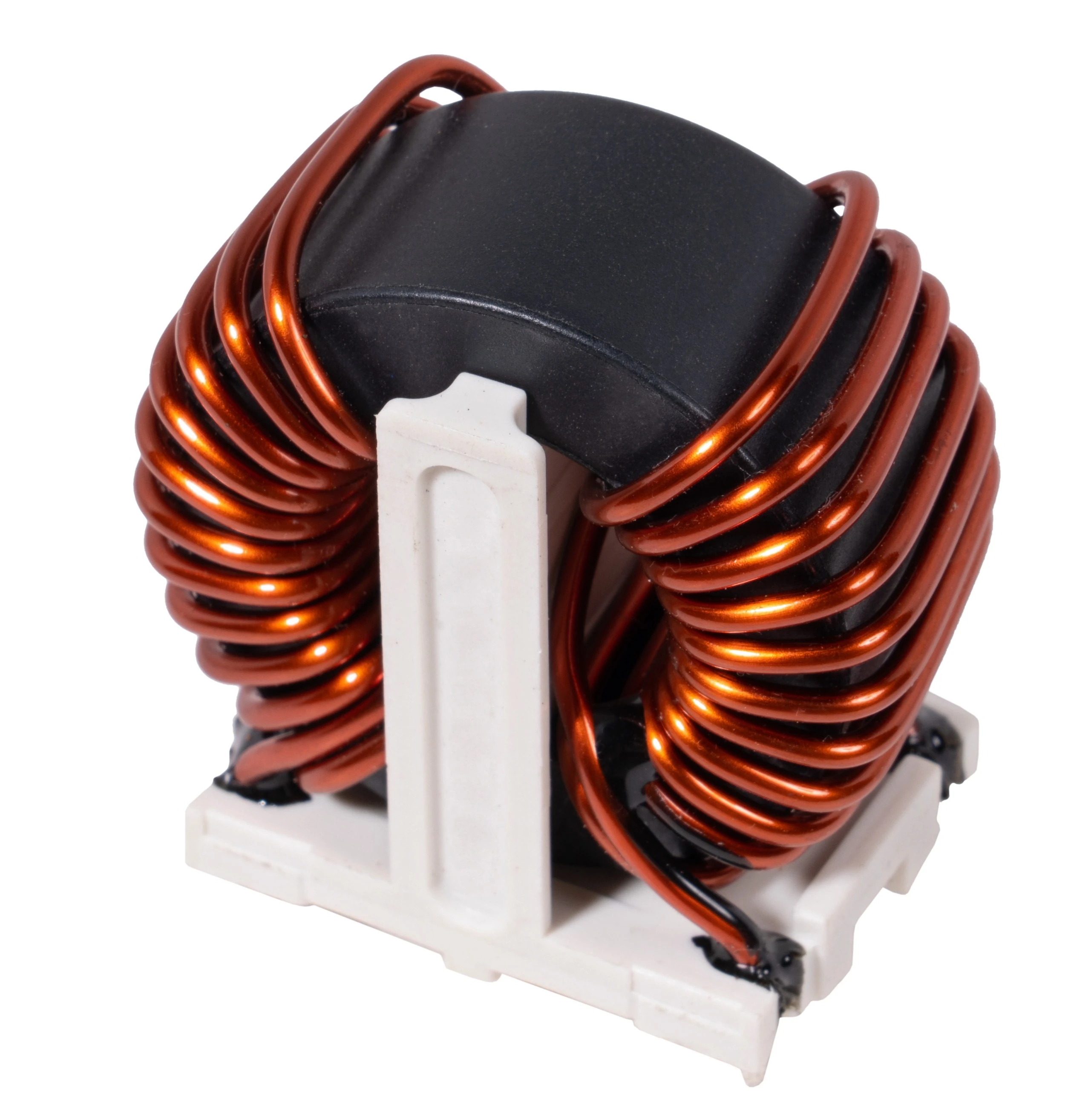
Ferrite core transformers are integral to power electronics and telecommunications, valued for their high efficiency and superior performance at high frequencies. In certain scenarios, however, reducing their operating frequency is necessary to minimize losses, enhance performance at lower frequencies, or meet specific design requirements. This blog outlines practical approaches to effectively lower transformer frequency while preserving efficiency and reliability.
Ferrite core transformers are engineered for high-frequency operation, typically in the kHz to MHz range, due to several advantages. Ferrite materials exhibit low core losses, with minimal hysteresis and eddy current losses, making them ideal for high-frequency applications. Operating at higher frequencies also enables the design of smaller transformers that maintain the same power handling capacity. Additionally, high frequencies reduce skin and proximity effects, which further enhances efficiency. However, certain applications, such as low-frequency power conversion, may necessitate a reduction in operating frequency to meet specific performance goals.
Lowering the frequency of ferrite core transformers introduces several challenges that impact performance. Ferrite materials are optimized for high frequencies, and reducing the frequency can lead to increased hysteresis losses, which diminish efficiency. Lower frequencies also require higher inductance, often resulting in larger transformer sizes to accommodate the necessary windings or core adjustments. Furthermore, without proper adjustments to the number of turns, there is a risk of core saturation, which can compromise the transformer's functionality and reliability.
One effective approach to reducing transformer frequency is to select a core material optimized for lower frequencies. Instead of standard ferrite, materials such as laminated silicon steel, suitable for very low frequencies like 50/60 Hz, or Sendust and powdered iron cores for intermediate frequencies in the kHz range, can be considered. To ensure optimal performance, core losses at the target frequency should be calculated using manufacturer datasheets, allowing for the selection of a material with minimal losses at the desired operating frequency.
Increasing the number of windings is another key strategy, as inductance is proportional to the square of the number of turns. By adding more turns, flux density can be reduced, helping to prevent core saturation at lower frequencies. However, this approach increases copper losses and may result in a larger transformer size, requiring careful consideration of trade-offs. The transformer equation, which relates voltage, flux density, core area, number of turns, and frequency, can be used to adjust the windings appropriately, striking a balance between avoiding saturation and minimizing resistance.
To mitigate saturation risks at lower frequencies, increasing the core's cross-sectional area can reduce flux density. This can be achieved by selecting a ferrite core with a larger effective area or by stacking multiple cores. While this approach helps maintain performance, it comes with the downside of increasing the transformer's overall footprint, which may impact the design's compactness. Careful selection of core size is essential to balance performance and space constraints.
Introducing an air gap into the ferrite core is another effective method to manage lower frequencies. An air gap increases permeability, enhances tolerance to DC bias, and reduces core losses, making it easier to operate at lower frequencies without saturation. However, this approach can introduce challenges such as increased fringing flux, which may lead to electromagnetic interference (EMI). To implement this strategy, the gap length should be calculated using the appropriate formula, and performance should be verified through simulation or prototyping to ensure optimal results.
In cases where a single transformer struggles to perform efficiently at low frequencies, using parallel-connected transformers can be a viable solution. This approach distributes power handling across multiple transformers, reducing the flux density in each core. To ensure effective operation, proper current sharing must be maintained by using transformers with matched inductances, preventing uneven load distribution and ensuring reliable performance.
Soft switching techniques, such as those used in resonant converters like LLC, zero-voltage switching (ZVS), or zero-current switching (ZCS), allow transformers to operate at lower effective frequencies while minimizing switching losses. By simulating resonant tank parameters, such as inductance and capacitance, for the target frequency range, designers can optimize the transformer's performance for low-frequency applications while maintaining high efficiency.
To achieve optimal results when reducing transformer frequency, thorough testing and validation are essential. Prototyping the transformer design and measuring core temperature, losses, and efficiency can help identify any issues early in the process. Additionally, optimizing the windings by using Litz wire can reduce the skin effect at higher currents, improving performance. Effective thermal management is also critical, as increased losses at lower frequencies may generate additional heat, requiring proper cooling mechanisms. Finally, leveraging simulation tools such as SPICE, ANSYS Maxwell, or JMAG can provide valuable insights into the transformer's performance, enabling precise adjustments to meet design goals.
